Unvented Cylinder D1 and D2 Pipework: Sizes and Rules
D1 is the short pipe from the relief valve to the tundish, 600mm at most. D2 drops 300mm, falls 1 in 200 and is sized from Table 3.1 of ADG.
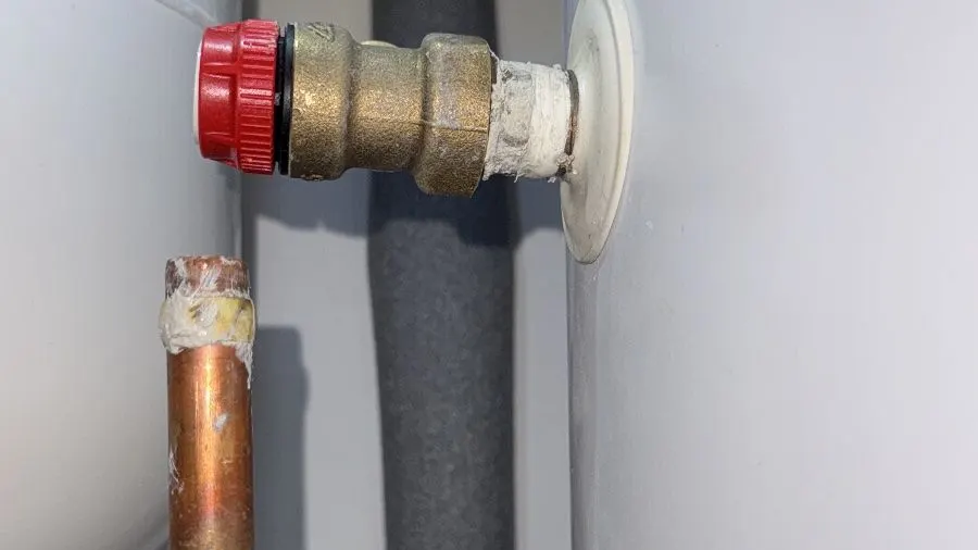
D1 is the short metal pipe from the relief valve to the tundish: no more than 600mm long and never smaller than the valve outlet. D2 runs from the tundish to a safe termination. It drops at least 300mm vertically before any bend, falls at 1 in 200 or steeper, and is sized from Table 3.1 of Approved Document G.
The funnel-topped fitting beside an unvented cylinder is the tundish, and the pipes on either side of it are the discharge pipework. Approved Document G calls them D1 and D2. They get squeezed in last, hidden behind a cupboard panel, and checked least. They also sit between a failed safety valve and a scalded person or a ruined ceiling.
This guide sets out what the document says for England: how long D1 can be, where the tundish goes, how D2 is sized, where it can end, and what a dripping tundish is telling you. The figures come from Approved Document G with the 2024 amendments. Scotland, Wales and Northern Ireland have their own documents and some numbers differ, so check the one that applies to your property.
⚠️ Scald risk. Approved Document G describes the discharge from these pipes as high temperature water and steam (paragraph 3.63). Do not put your hand under a tundish or discharge pipe, do not cap or plug it, and do not stand under an outside termination while the cylinder is discharging. If someone is scalded, the NHS advises holding the burn under cool running water for 20 minutes, and calling 999 or going to A&E if it is large or deep, or on the face, genitals or bottom.
Unvented Cylinder D1 and D2 Pipework Explained
D1 is the short length of metal pipe between the cylinder's safety valve and the tundish. D2 is everything after the tundish, down to the point where the water leaves the building or reaches a drain. Paragraph 3.50 says safety devices such as temperature relief valves discharge through D1 to a tundish, and the rest of the guidance keeps that route short, visible and big enough to carry the flow.
An unvented cylinder holds water at mains pressure with no open vent. If the thermostats and the cut-out all failed, the temperature and pressure relief valve would open to stop the vessel overheating. That water has to go somewhere safe, you have to be able to see it happening, and the pipe carrying it must not restrict the flow so much that pressure builds behind it. D1, the tundish and D2 each cover one of those jobs.
The work itself is regulated. Installing an unvented system is notifiable building work (paragraph 3.41). If the installer is registered with a competent person scheme, the work does not need notifying in advance, and the installer self-certifies it instead (3.42). Our G3 unvented cylinder guide covers the ticket, the safety devices and the paperwork. This article stays with the pipes.
D1 Pipework: Size and the 600mm Limit
D1 must be no smaller than the outlet of the safety valve (paragraph 3.51), and there can be no more than 600mm of pipe between the valve outlet and the tundish (3.54). D1 is a metal pipe. Table 3.1 is written for copper, so that is what the sizes below assume.
Many websites quote 500mm. That figure comes from the Scottish building standards handbook, which puts the air break not more than 500mm from the vessel relief valve. In England the number is 600mm of pipe. If you are working in London, use 600mm, and if you are reading a forum post, check which country it was written for.
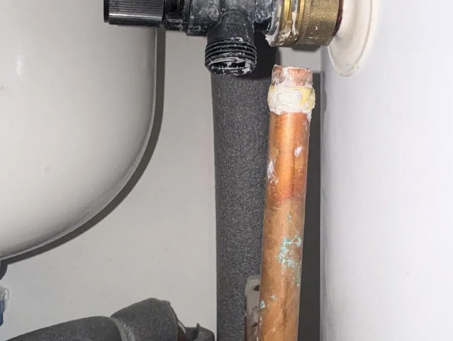
D1 sizes come from the valve, not from the cylinder volume. Table 3.1 gives a minimum D1 of 15mm for a G1/2 outlet, 22mm for G3/4 and 28mm for G1. The cylinder's installation manual states which valve is fitted. Where the manufacturer specifies something larger, follow the manufacturer.
Tundish Position and Air Gap
The tundish must be vertical, in the same space as the cylinder, as close as possible to the safety valve and lower than it, with no more than 600mm of pipe between them (paragraph 3.54). Any discharge should be visible at the tundish (3.55). The note under 3.54 says the tundish should incorporate a suitable air gap to comply with the Water Supply (Water Fittings) Regulations.
Approved Document G gives no millimetre figure for that gap. A tundish is a manufactured fitting with the gap built in, so the practical rule is to fit a proper tundish the right way up and follow the instructions that come with it and with the cylinder. If someone quotes you a specific gap in millimetres, ask which product or standard it comes from.
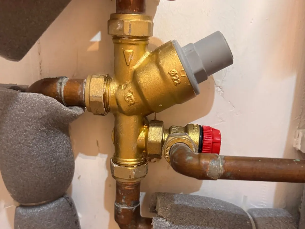
Visibility is the part most often defeated on site. A tundish boxed in behind a fixed panel, or fitted in a loft void nobody visits, meets the letter of the position rule and fails its purpose. If you cannot see into it without taking something apart, the first sign of a discharge will be a stain on the ceiling below.
Megaflo tundish notes
Megaflo is the brand we are asked about most, so here is what the Eco Plus fitting instructions add to the regulations. The tundish must be visible to the end user and installed away from electrical components. Discharge pipes must run continuously downward in a frost-free environment and stay open to the atmosphere. Plastic D2 is acceptable only if tested to a minimum of 110°C, and a soil stack must be able to handle 99°C or more.
The same instructions list the factory settings: temperature and pressure relief valve at 90°C and 10 bar, pressure relief (expansion) valve at 8 bar, pressure reducing valve at 3.5 bar and expansion vessel pre-charge at 3 bar. Other brands use different numbers, so check the installation manual for your model rather than trusting a general article, this one included.
D2 Pipework: 300mm Drop, 1 in 200 Fall and Sizing
D2 must have a vertical section at least 300mm long below the tundish before any elbow or bend (paragraph 3.56a), then a continuous fall of at least 1 in 200 (3.56b). That is 5mm of drop for every metre of run, so a 6m horizontal section must finish at least 30mm lower than it starts. There should be no flat spots and no rises.
D2 is metal, or another material shown to withstand the discharge temperature and clearly and permanently marked with its product and performance standard, such as the relevant part of BS 7291-1 (3.57). Plastic that cannot show that marking has no place on this pipe.
Sizing is the rule people get wrong. D2 has to be at least one pipe size larger than the valve outlet, unless its resistance exceeds that of a straight pipe 9m long. A run with a resistance of 9 to 18m needs to be at least two sizes larger, and 18 to 27m at least three (3.58). Every bend adds resistance, which Table 3.1 gives as a length you subtract from the allowance.
| Valve outlet | Minimum D1 | D2 size | Maximum run (straight pipe) | Allowance per bend |
|---|---|---|---|---|
| G1/2 | 15mm | 22mm | Up to 9m | 0.8m |
| 28mm | Up to 18m | 1.0m | ||
| 35mm | Up to 27m | 1.4m | ||
| G3/4 | 22mm | 28mm | Up to 9m | 1.0m |
| 35mm | Up to 18m | 1.4m | ||
| 42mm | Up to 27m | 1.7m | ||
| G1 | 28mm | 35mm | Up to 9m | 1.4m |
| 42mm | Up to 18m | 1.7m | ||
| 54mm | Up to 27m | 2.3m |
Table 3.1 is based on copper tube, and the document notes that plastic pipes may have a different bore and resistance. An alternative sizing method is in BS 6700:2006+A1:2009 Annex D, section D.2. If one common discharge pipe serves more than one system, it must be at least one pipe size larger than the largest D2 connected to it (3.59).
Worked example: G1/2 valve
This is the example Approved Document G itself uses. A G1/2 valve has 7m of 22mm D2 with four elbows. The 22mm column allows 9m, and each elbow costs 0.8m, so four elbows use 3.2m. That leaves 5.8m of permitted length, which is less than the 7m actual run, so 22mm fails. At 28mm the allowance is 18m and four elbows at 1.0m use 4m. That leaves 14m, well over the 7m needed, so 28mm passes.
Worked example: G3/4 valve
This one we worked out ourselves from the same table. A G3/4 valve has 8m of D2 with five elbows. At 28mm the allowance is 9m and each elbow costs 1.0m, so five elbows use 5m, leaving 4m. The run is 8m, so 28mm fails. At 35mm the allowance is 18m and each elbow costs 1.4m, so five elbows use 7m, leaving 11m. That covers the 8m run, so 35mm passes.
Bends are expensive, and the fix is usually one pipe size up rather than a rebuild. If you inherit a D2 that someone fitted in the same size as D1 because it was easy to match, this is the check that catches it.
Where the Discharge Pipe Can End
D2 must end in a safe place where nobody nearby is at risk from the discharge (paragraph 3.61). The document gives three acceptable examples (3.62):
- A trapped gully, with the end of the pipe below a fixed grating and above the water seal.
- Low level outside: a downward discharge up to 100mm above an external surface such as a car park, hard standing or grass, with a wire cage or similar guard that stops contact while keeping the discharge visible.
- High level: into a metal hopper and metal downpipe with the end of the pipe clearly visible, or onto a roof that can withstand high temperature discharges and sits 3m from any plastic guttering that would collect it.
Flats make this awkward. A first-floor or basement cylinder may have no outside wall within reach, and the outside wall may belong to the freeholder, so you cannot simply drill through it. Check with the managing agent before the route is designed, not after the pipe is in.
The soil stack is the usual alternative, with conditions. The discharge pipe should not connect to a soil stack unless the stack can safely withstand the temperature of the discharged water, and then the connection must meet four requirements (paragraph 3.60). It needs a mechanical seal with no water trap, so water gets in but foul air cannot escape through the tundish. It must be a separate branch with no sanitary appliances connected. If the branch is plastic, it must be polybutylene (PB) or cross-linked polyethylene (PE-X). And it must be marked along its length with a warning that no sanitary appliances are to be connected.
A discharge that ends in a sealed drain, or somewhere nobody ever looks, defeats the rule even if every measurement above is right. If you are not sure whether an existing route is compliant, an engineer from our G3 unvented cylinder service can inspect it and tell you which of these figures it fails.
Is a Dripping Tundish Dangerous?
A dripping tundish is not automatically dangerous, but it is always telling you something. The tundish shows you that a valve has opened, not which one, so the table below follows the fault chart in the Megaflo Eco Plus instructions. Other makes will differ, so check your own manual.
| What you see | What Megaflo's fault chart links it to | What to do |
|---|---|---|
| Water from the expansion valve now and then, usually as the cylinder heats | Air volume in the expansion vessel has reduced, or the 8 bar expansion valve is faulty | Have the vessel pre-charge checked at the next service |
| Water from the expansion valve that never stops | The 3.5 bar pressure reducing valve is not working correctly, or the expansion valve seat is damaged | Book an engineer this week |
| Water from the T and P valve that never stops, and very hot | Thermal control failure | Switch off the immersion and the boiler, keep clear and call a G3-qualified engineer now |
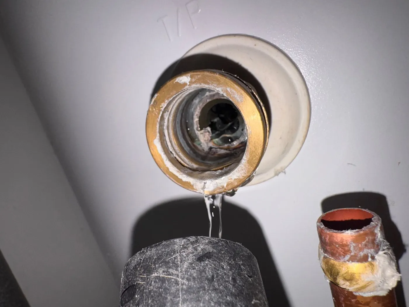
For the hot water case, the Megaflo chart says not to turn off the water supply, and the discharge pipe must not be blocked or used for any other purpose. Approved Document G's own warning label for unvented cylinders says that if hot water flows from the discharge pipe, you should switch the heater off and contact the installer (paragraph 3.24). If the room is filling with steam, leave it and call 999 if anyone is at risk.
The full diagnosis by source, covering the temperature and pressure valve, the expansion vessel, the immersion gasket and the anode, is in our guide to why a Megaflo leaks, and the pre-charge numbers are in the expansion vessel pressure guide. If the valve itself has failed, our T and P valve replacement page covers that job.
When to Call a Professional
Call a G3-qualified engineer when the tundish is discharging hot water, when it drips constantly, and before you change any part of the discharge route. Approved Document G tells users not to remove or adjust components of an unvented cylinder, and D2 is part of the route a relief valve depends on. Whether a particular alteration has to be notified to Building Control depends on the work, and a G3-qualified installer can tell you. You can look at the tundish, photograph it and note when it drips. Everything past that belongs to someone with the ticket.
Tundish Dripping or Discharge Pipework Not Right?
G3-qualified engineers across London. £60 call-out fee at any hour for ordinary emergency work, waived for landlords, property managers and scheduled work. We check D1, the tundish and D2 against Approved Document G and tell you plainly what needs changing.
Call 0207 046 1363You can also reach us on WhatsApp at 07456 975436. Send a photo of the tundish and the pipe run so we can see what we are dealing with before we arrive.
Frequently Asked Questions
What is D1 and D2 on an unvented cylinder?
How far can the tundish be from the relief valve?
What size should the D2 discharge pipe be?
Is it normal for a tundish to drip?
Can the discharge pipe go into a soil stack?
Can I alter the discharge pipework myself?
John Alexander N., Director, Emergency Repairs London
Key Takeaways
- D1 can be no more than 600mm of pipe from the valve outlet to the tundish (Approved Document G, paragraph 3.54), and no smaller than the valve outlet (3.51)
- D2 must run at least 300mm vertically below the tundish before any elbow or bend (3.56a), then fall continuously at 1 in 200 or steeper (3.56b), which is 5mm per metre
- Table 3.1 sizes D2 from the valve outlet: a G1/2 valve takes 22mm D2 up to 9m, 28mm up to 18m and 35mm up to 27m, with each bend using up 0.8m to 1.4m of that allowance
- A common discharge pipe serving more than one D2 must be at least one size larger than the largest D2 joined to it (3.59)
- D2 can end at a trapped gully, at low level up to 100mm above an external surface with a guard, or at high level into a metal hopper or onto a roof 3m clear of plastic guttering (3.62)
- Unvented work is notifiable to Building Control before it starts, and installers on a competent person scheme self-certify it (3.41 and 3.42)
